104 Results
View results:
Sort by:

RWIND 2 and RFEM 6 can now be used to calculate wind loads from experimentally measured wind pressures on surfaces. Basically, two interpolation methods are available to distribute pressures measured in isolated points across the surfaces. The desired pressure distribution can be achieved using the appropriate method and parameter settings.

The national parameters of EN 1992‑1‑1 for each country can be exported from RF‑/CONCRETE, RF‑/CONCRETE Columns, and RF‑/FOUNDATION Pro. To do this, there are interfaces with MS Excel, OpenOffice, and CSV. By exporting the national parameters, you can edit them in (for example) MS Excel, and display possible differences between the individual National Annexes clearly (see the image).
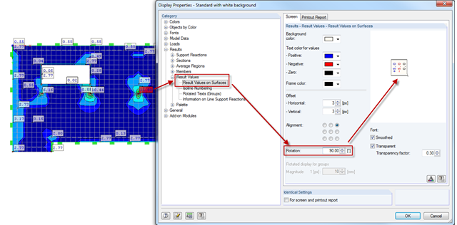
Sometimes, it is necessary to rotate graphics in the printout report. In order to also display the result values correctly, you can rotate the results by the respective angle using the Display Properties dialog box. As usual in Display Properties, this setting is to be done separately for the screen view and the printout report.
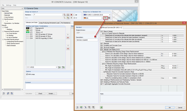
In order to meet the requirements for the parameters of special buildings modified according to standard adjustments, you can create new National Annexes from an existing one. To do this, copy the National Annex and adjust the parameters to the requirements.
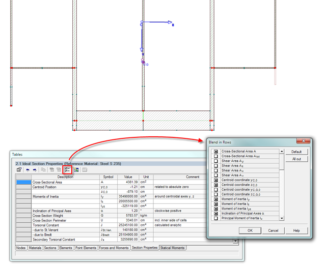
The result window of the cross-section properties can be adjusted individually using the [Filter] button in the table menu bar. You can then activate or deactivate the individual cross-section parameters in the dialog box.
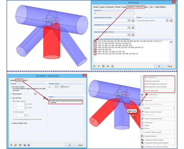
If intersections created in RFEM 4 are opened in an RFEM 5 file, the file management of intersections remains in the old format for compatibility reasons. Thus, the individual partial surfaces of the intersection can be activated or deactivated using only the "Integrated/Components" tab, all partial surfaces can only have the same thickness, and it is impossible to use the separate FE mesh refinement for the individual surface components.

When calculating foundations according to EC 7 or EC 2, different foundation types or sizes are usually used in one object. However, boundary conditions like the soil parameters, the materials for foundations, concrete covers, and the load combinations selected for design remain the same for all foundations, as a rule.
For the superposition or combination of loads, the German standard DIN 18008 refers to DIN 1055‑100. This also applies for the individual parameters of climatic loads to be transferred. In this case, it is possible to summarize the temperature change and meteorological pressure change in a single load and to define the local altitude change as a permanent load.

Plate girder is an economical choice for long spans construction. I-section steel plate girder typically has a deep web to maximize its shear capacity and flange separation, yet thin web to minimize the self-weight. Due to its large height-to-thickness (h/tw) ratio, transverse stiffeners may be required to stiffen the slender web.
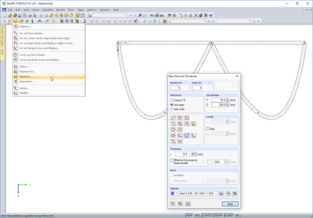
In addition to arcs and circles, SHAPE-THIN 8.xx allows you to model the following curved cross-section parts: ellipses, elliptical arcs, parabolas, hyperbolas, splines, NURBS (non-uniform rational B-Spline).
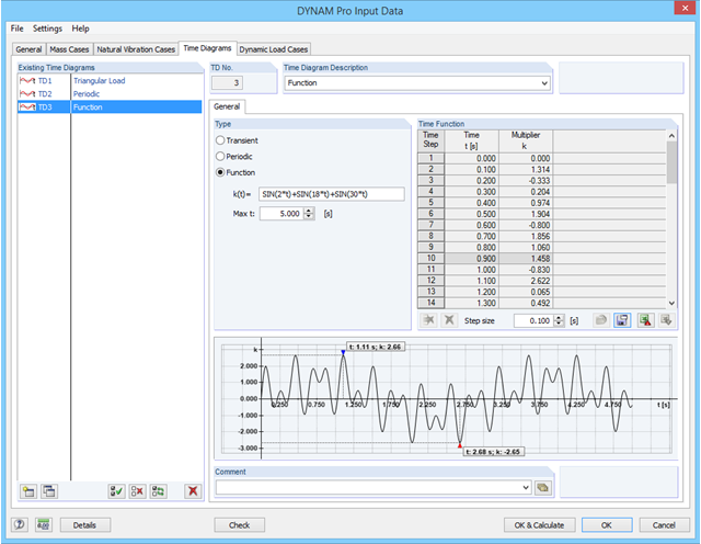
In RF-/DYNAM Pro - Forced Vibrations, you can define time diagrams directly as functions in an edit field. The parameter t is reserved for the time steps, but apart from that, all parameters as defined in the "Edit Parameter" dialog can be used in RF‑/DYNAM Pro.

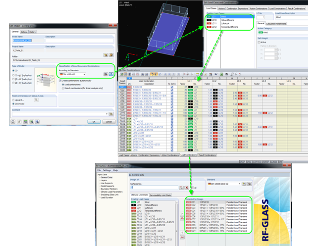
The dialog box for editing load or result combinations is a non-modal dialog box. This means that after you open this dialog box, you can edit the combinations outside the dialog box as well. For manually defining or editing a combination, a separate dialog box can be opened parallel to the "Edit load cases and combinations" dialog box.
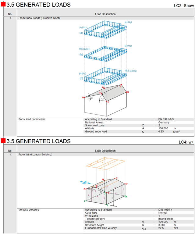
In addition to the general information about the generated snow and wind loads in the form of tables, the corresponding schematic sketches are also available in the printout report of RFEM and RSTAB now. These are displayed separately for each load case.
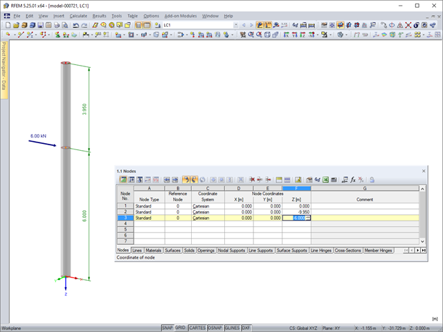
Model and load objects can be defined graphically or in tables, or they can be created using parameters (see the manual). With this parameterized input, you can also access the cells of certain tables of the program. In this way, it is possible to link a load parameter with a model data parameter, for example. The reference is created by the $ sign.

After running an analysis in RF-/STEEL AISC, the mode shapes for sets of members can be viewed graphically in a separate window. Select the relevant set of members in the result window and click the [Mode Shapes] button.
In RF-/DYNAM Pro - Natural Vibrations, you can import axial forces and stiffness modifications from any Load Case (LC) or Load Combination (CO). You can modify material, cross‑section, member, and surface properties and activate these modifications in the LC/CO calculation parameters.
If a bending load of a brittle beam element (an unreinforced concrete beam) is increased by means of the bending capacity, the structure responds by breaking the cross-section and the member is separated into two segments. At the time of the failure, the broken part suddenly loses its potential to transfer the bending moment. Due to the segmentation, the critical part also fails to transfer the other force types, such as axial forces.
In the Formula Editor environment, you can specify any parameters (lengths, force values, and so on) to control load and geometry data in the modeling.
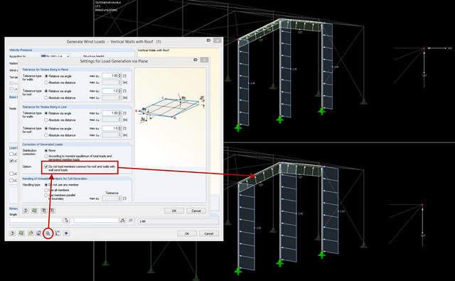
When using the wind load generator for vertical walls with a roof, it may be necessary to load the edge members on eaves or on a gable only with the wind loads of the roof. For structural reasons, the horizontal wind loads should apply to the vertical walls by the facade. In previous versions, it was necessary to apply the wind loads separately to the walls and the roof with the corresponding generators and exclude the unwanted members.
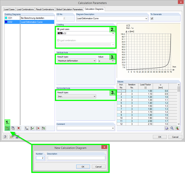
To record and display a relation between the various calculation results, you can use the calculation diagrams. You can create and display them using the "Calculation Parameters" dialog box available under "Calculation" → "Calculation Parameters".